Tampilkan postingan dengan label Cisco. Tampilkan semua postingan

Senin, 07 Maret 2022

Static Routing Packet Tracer

Static Routing Packet Tracer

Static Routing adalah router yang memiliki tabel routing yang disetting secara manual oleh administrator jaringan. Static Routing ini memiliki pengaturan routing paling sederhana dalam sebuah jaringan. Penggunaan routing statik dalam jaringan yang kecil bukanlah suatu masalah, tapi jika dalam jaringan yang besar memerlukan konfigurasi yang ribet karena harus disetting manual.

Cara Kerja Static Routing ada 3 :
1. Tabel routing dibuat secara manual oleh administrator jaringan.
2. Router melakukan routing berdasar informasi yang diterima dari tabel routing.
3. Administrator menggunakan perintah ip route secara manual untuk konfigurasi router.

Kelebihan Static Routing :
1. Static Routing lebih aman daripada Dynamic Routing
2. Static Routing lebih kebal terhadap para hacker

Langkah – langkah konfigurasi Static Routing di Cisco Packet Tracer :

1. Buka Cisco Packet Tracer

2. Buat topologi-nya seperti di bawah ini

3. Konfigurasi IP pada PC. Caranya klik pada PC->Desktop->IP Configuration

PC 0 :
IP Address -> 192.168.10.1
Subnet Mask -> 255.255.255.0
Gateway -> 192.168.10.2 (IP Router)
PC1 :
IP Address -> 192.168.20.1
Subnet Mask -> 255.255.255.0
Gateway -> 192.168.20.2 (IP Router)
PC2 :
IP Address -> 192.168.30.1
Subnet Mask -> 255.255.255.0
Gateway -> 192.168.30.2 (IP Router)

4. Konfigurasi IP pada Router. Caranya klik pada Router->CLI

->enable => masuk ke router
#conf t => masuk menu konfigurasi
#interface gig0/0 => konfigurasi interface gigabit ethernet 0/0
#ip address 192.168.10.2 255.255.255.0 => menambahkan ip dan subnet pada interface gig0/0
#interface se0/1/0 => konfigurasi interface serial 0/1/0
#ip address 10.10.10.1 255.255.255.0 => menambahkan ip dan subnet pada se0/1/0
#no shutdown => mengaktifkan interface yang telah di konfigurasi

Lakukan langkah yang sama pada Router1 dan Router2 dengan IP :
Router1 :
-Interface Gig0/0 -> IP = 192.168.20.2 -> Subnet = 255.255.255.0
-Interface Se0/1/0 -> IP = 10.10.10.2 ->Subnet = 255.255.255.252
-Interface Se0/1/1-> IP = 20.20.20.1 -> Subnet = 255.255.255.252
Router2 :
-Interface Gig0/0 -> IP = 192.168.30.2 -> Subnet = 255.255.255.0
-Interace Se0/1/0 -> IP = 20.20.20.2 -> Subnet = 255.255.255.252

5. Konfigurasi Static Routing pada Router

Untuk setting static routing di cisco packet tracer menggunakan perintah :
#ip route [destination] [subnet] [next hop address]
Keterangan :
-ip route : perintah membuat tabel routing static
-destination : network jaringan yang dituju
-subnet : subnet mask jaringan yang dituju
-next hop address : ip dari router yang akan dilewati

Lakukan hal yang sama pada Router1 dan Router2 dengan ketentuan :
Router 1 :
#ip route 192.168.10.0 255.255.255.0 10.10.10.1
#ip route 192.168.30.0 255.255.255.0 20.20.20.2
Router2 :
#ip route 192.168.10.0 255.255.255.0 20.20.20.1
#ip route 192.168.20.0 255.255.255.0 20.20.20.1

Advertisements

6. Lakukan pengecekan, bisa dengan menggunakan ping pada CommandPrompt di PC atau dengan menggunakan surat

Baca selengkapnya

Minggu, 17 Juli 2016

Network and IP address calculator

Network and IP address calculator

ip calculator


Network and IP address calculator

This page requires Javascript to be enabled!

IP/Netmask: (input format examples: 10.0.0.5/24 or 10.0.0.5 255.255.255.0)

result:
Usable addresses:
Mask: =
Mask as hex:
Network:
First usable:
Last usable:
Broadcast:


Converters for Network and IP address

Subnet netmask dotted decimal to CIDR notation (bits format)


result: /


Class C subnet calculator

number of subnets to create:

result:

mask: / dotted dec. mask:
amount of usable host addresses per subnet:
addresses in each subnet:


Number of required addresses to netmask

number of addresses needed:

result:

mask: / dotted dec. mask:
usable amount of addresses:


Dotted decimal IP-address or mask to binary and hex


result:

Bin:
Hex:


Hex IP-address or mask to dotted decimal


result:

dotted decimal:
Bin:


IP-address bit-complement (inverted IP) calculator

result:


Network Mask to amount of usable addresses

Mask: /

result:

Usable amount of addr: Total number of addr:
Netmaks in dotted decimal format:


Number converter: decimal => bin, hex

Dec:


result:

Bin:
Hex:
 

Number converter: binary => dec, hex

Bin:


result:

Dec:
Hex:
 

Number converter: Hex => dec, bin

Hex:


result:

Dec:
Bin:


IP Multicast address ranges

All multicast addresses can easily be recognized because they start with the bit pattern "1110".

224.0.0.0 - 224.0.0.255 Well-known multicast addresses, control channels
224.0.1.0 - 238.255.255.255 Globally-scoped (Internet-wide) multicast addresses
239.0.0.0 - 239.255.255.255 Local multicast addresses

Special and private address ranges

Private address ranges are not routed on the Internet and can be freely allocated in any private network. NAT (network address translation) is required when connecting such a network to the Internet.

Private network addresses (RFC1597/RFC1918 addresses):
10.0.0.0 - 10.255.255.255 A 24-bit block, /8, class A network
172.16.0.0 - 172.31.255.255 A 20-bit block, /12, set of 16 contiguous class B network numbers
192.168.0.0 - 192.168.255.255 A 16-bit block, /16, set of 255 contiguous class C network numbers

Special addresses:
127.0.0.0 - 127.255.255.255 Special address range for the localhost. You can normally not use those addresses for anything else. 127.0.0.1 is generally assigned to the loopback device
0.0.0.0 Special host address commonly reserved for the default route

Overview of common subnets and masks

Mask Hosts  Usable Netmask          Hex Mask
/30  4      2      255.255.255.252  fffffffc  this is 1/64 of a Class C net
/29  8      6      255.255.255.248  fffffff8  this is 1/32 of a Class C net
/28  16     14     255.255.255.240  fffffff0  this is 1/16 of a Class C net
/27  32     30     255.255.255.224  ffffffe0  this is 1/8 of a Class C net
/26  64     62     255.255.255.192  ffffffc0  this is 1/4 of a Class C net
/24  256    254    255.255.255.0    ffffff00  this is a Class C net
/23  512    510    255.255.254.0    fffffe00  these are 2 Class C net
/22  1024   1022   255.255.252.0    fffffc00  these are 4 Class C net
/21  2048   2046   255.255.248.0    fffff800  these are 8 Class C net
/20  4096   4094   255.255.240.0    fffff000  these are 16 Class C net
/19  8192   8190   255.255.224.0    ffffe000  these are 32 Class C net
/18  16384  16382  255.255.192.0    ffffc000  these are 64 Class C net
/17  32768  32766  255.255.128.0    ffff8000  these are 128 Class C net
/16  65536  65534  255.255.0.0      ffff0000  these are 256 Class C net = Class B net


© Guido Socher, version 2015-12-18
This page is operting system independent. It only requires a javascript capable webbrowser. You can install it locally on your PC just by saving this html page.

Baca selengkapnya
Daftar ISI

Daftar ISI

Memuat…
Baca selengkapnya

Jumat, 15 Juli 2016

Cisco IOU on GNS3

Owrait, sebelum mulai installasi, pastikan anda mempunyai semua bumbu yang dibutuhkan, berikut ini adalah bumbu2nya :
1. GNS3 (Saya pake yang v 1.3.0)
2. Virtualbox
3. GNS3 IOU VM (Versi disesuaikan dengan GNS3)
4. IOU Images (cari yang L2 dan L3 sendiri yah)

5. IOURC (License IOU GNS3)

Ini skrinsotnya

Langkah installasi :
1. Install GNS3, udah jago lah yaa :D
2. Install virtualbox, ini juga udah pada bisa kan?
3. Install GNS3 IOU VM ke virtualbox. Caranya extract dulu file GNS3 IOU VM.rar, kemudian buka GNS3 IOU VM.ovf . Untuk setting RAM, CPU dll saya biarkan default. Klik import.


4. Jalankan VM tersebut, tunggu sampai selesai booting. Login menggunakan User : root Pass : cisco. Kemudian check ip addressnya menggunakan command ifconfig.

5. Upload IOU images ke IOU VM, caranya buka ip address dari VM tersebut menggunakan browser di port 8000. Di sini ip address VMnya adalah 192.168.56.102, maka di browser saya buka 192.168.56.102:8000. Klik "upload images" kemudian masukkan IOU images L2 dan L3 nya.
Copy path file yang muncul di bawahnya ke notepad karena nanti path inilah yang akan kita gunakan ketika ingin di import ke GNS3


6. Buka GNS3, klik Edit -> Preferences -> Server.
- Enable local server
- Host binding : pilih IP Address yang satu network dengan VM kita
- Port : 8000


7. Klik pada Remote server
- Host : masukkan ip address VM kita
- Port : 8000, lalu klik Add

8. Selanjutnya, masukkan iourc.txt ke kolom license di GNS3. Klik IOS on UNIX -> General -> masukkan iourc.txt pada Any server.

9. Terakhir, tinggal tambahkan image nya di tab IOU devices. Untuk path nya, tinggal copas dari notepad yang tadi. Untuk server type = remote.

Warning : Jangan lupa klik Apply dulu sebelum klik OK. Kalo langsung OK ntar ga ke save dan harus ngulang lagi -_-))

Mungkin nanti setelah di klik OK akan muncul kek gini dan ga selese2, padahal udah ditunggu sambil bikin mie sedap rebus rasa soto ayam sampe abis dimakan .. Huft.
Nah, kalo kejadian, silakan close dulu GNS3nya, terus buka lagi. Aman kok ..

Testing...

Oh iya baru inget, dengan L2 IOU, kita punya switch di GNS3 sekarang hahaha.

Source: http://blog.ariessadewa.id/2015/12/cisco-iou-on-gns3.html
Baca selengkapnya

Lab Setup on GNS3 Using IOU

Step 1: 
First of all download the latest version of GNS3 from the below link and install it :
Note: Just make a community account to download the software
GNS3 Latest Version Download Here

Step 2: 
Just start the installation process like you do for other software.
Note: Check all the packages in the below windows during the installation process.


Step 3:
Now the next step in the process will be installation of Oracle Virtual Box. The latest verssion of the software can be downloaded by following the below link and download the Windows Version as this process is for Windows only. Install the software as you normally install some other software.

Oracle VirtualBox Download Here

Step 4:
Now download GNS3 IOU VM that will be then imported into the VirtualBox in the coming up steps. GNS3 IOU VM can be downloaded by following below link:

GNS3 IOU VM Download Here

Step 5:
Next download the iou images. Those images will be uploaded into the GNS3 IOU VM later on.
I am using below 2 images:
For L2->>> i86bi-linux-l2-adventerprise-15.1b.bin
For L3->>> i86bi-linux-l3-adventerprisek9-15.4.1T.bin

IOU Images are for CISCO internal use only but can be found on Torrent.

Step 6:
A license file will be required later in the process so that can be downloaded by following the below link:

License File Download Here

 Step 7:
All prerequisites have been completed as per my knowledge :P.
In this step we will be importing the VM into VirtualBox and necessary settings will be done.

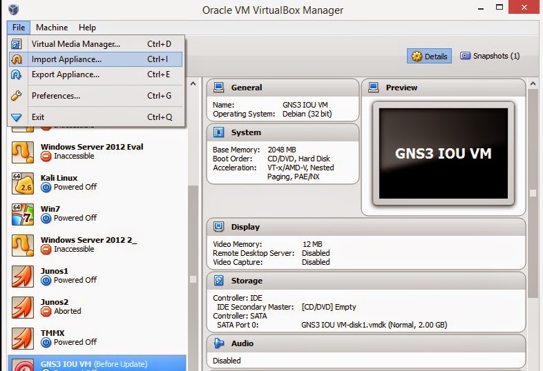
          7a. Open VirtualBox Manager and Go to File > Import Appliance.
          
          7b. Give path to the IOU-VM you have downloaded in the below Window:
            

             7c. Click Next and then an appliance Settings window will appear. Just do nothing and     proceed with the Import button. Import process will start.

             7d. Right click on the GNS3 IOU VM from the Virtual Box Manager and then click on Settings. Below window will appear. Select Network from the left side Menu and Please make sure that Network Adapter is set to "Host-Only Adapter" and the selected Name of the Adapter is of VirtualBox Adapter "VirtualBox Host-Only Adapter":


 Step 8:
 Switch ON the IOU VM from Virtualbox and note down the IP address shown on login screen to upload the IOU L2/L3 images that you have downloaded in Step 5. Please note that IP is not always same. It can be different in your case.


Open it into the browser and click on Upload Images from the below screen and upload the images into the vm to use them in GNS3.


Copy the complete path of you image as shown in the browser screen, later it will be used for configuring the GNS3. I have highlighted my image in the below image.


 Step 9:
 From your network connections configure your Virtualbox Adapter with the IP with the same network, the IOU VM is of. e.g in my case 192.168.56.101 was the vm IP so i assigned 192.168.56.223 as shown below.


 Step 10:
Open GNS3 for the configuration of L2 and L3 images and go to Edit > Preferences, preferences window will open now. Click on the 2nd option in the left navigation pane i-e server. In this screen select the IP of the Virtualbox adapter in the "Host Bindings field" as in my case I have selected the adapter as configured above.


In this same section select "Remote Servers" Tab and then configure the IP of the IOU VM in it and add it as shown in below image.


 Step 11:
In this step we will be creating Switch and Router devices but before that we will be importing the license file that we have downloaded earlier.For this just click on "IOS on UNIX" and give path to the license file as shown in below image.


Navigate to the "IOS on UNIX" >  "IOU devices" and click on "New" then follow the below images.


In the below screen you will do the following settings for Router and Switch and then Finish it each time:
 ROUTER:
Name: R
IOU image: The l3 image link you copied from browser earlier
Type: L3 image

SWITCH:
Name:SW
IOU image: The l2 image link you copied from browser earlier
Type: L2 image

 Step 12:

Your devices are now ready to use just add them to make your custom topology. Shown below are the added devices.


IOS Images can also be added from Dynamips > IOS Routers section and can be used with the IOU Switches.  Please let me know via comment if you have any problem while setting up the Lab.
Source: Network club
Baca selengkapnya

Nexus Modules/LineCards Naming Conventions


Hi Guys, Finally I am back!! I have been into Cisco Data Center Technologies from a long time. The first and most important thing  one should know is to get an understanding of how to take a brief specification information of the Nexus Switches Chassis and I/O Modules from the names/Model numbers. As I am more into the 7k series switches so I shall be taking examples of 7k switches
Chassis Identification:
Exact Model number tells two things:
1. Series of Nexus Switch/Chassis
2. Number of Slots in the chassis
For Example the 7k series has following models.
7004- 7000 Series and 4 Slots
7009- 7000 Series and 9 Slots
7010- 7000 Series and 10 Slots
7018- 7000 Series and 18 Slots
7702- 7700 Series and 2 Slots
7706- 7700 Series and 6 Slots
7710- 7700 Series and 10 Slots
7718 - 7700 Series and 18 Slots
Modules Identification:
Line Card Name will give you a bunch of information about its specifications. Below is one of the Line Card name taken as an example:
N77-M348XP-23L
N77   M3  48  X  P  23L 
N77 / N7K
Its indicates the type of chassis. N77 is 7700 chassis and N7K is 7000 chassis
M3 / M2 / M1 / F2 / F3
Indicates the series of Linecard. Detailed comparison chart can be seen on below link:
48
Indicates the number of ports on the linecard.
X / F / C / G
Indicates the speed of ports:
G is 1 Gig 
X is  10 Gig
F is 40 Gig
C  is 100 Gig
T / P / S / 2 / Q / K
This will tell you the type of interface. 
T is RJ45
S is SFP
P is SFP+
Q is QSFP+
K is Cisco CPAK
2 is X2
23L
The first digit (2) is the minimum number of fabric modules required for the card to operate, while the last digit (3) is the number of fabric modules required for the card to operate at maximum capacity.
Additionally, if the module has an additional "L" at the end, it designates that the module is a XL module. Primarily found on M1/M2 cards, and specifies that the card has extended hardware ressources (more routes, more MAC addresses etc.).
 
Source : Network Club
Baca selengkapnya

Sabtu, 09 Juli 2016

Seting ASA firewall dan ASDM di GNS3

One of the topics that is tested on the CCNA security exam is the adaptive security service manager (ASDM) of the Cisco ASA. This article will walk you through “installing” the ASDM on a Cisco ASA through GNS3. This will be helpful to those who want to familiarize themselves with the ASDM interface (the way we have been doing in the CCP series).
We will need a TFTP server, the ASDM image file, and the ASA we want to install it on. Our lab setup will contain just one ASA and one host (my laptop), which will act as both the TFTP server and the computer we will use to launch the ASDM when finished. The GNS3 topology is shown below:

Notice that I have used a switch to connect the host and the ASA because GNS3 does not support connecting a cloud/host directly to an ASA. The switch is just an “Ethernet switch” and all the ports are in the same VLAN (although you can change that).
The first thing we want to do is to make sure that the host and the ASA can communicate. We will use the 192.168.10.0/24 subnet.

Notice that, even though in the GNS3 topology the ASA interfaces are identified with “e” (signifying Ethernet?), they are actually Gigabit Ethernet interfaces. The ping also reveals that I can communicated with my host PC (192.168.10.10).
Now that we have communication, the next thing we need to do is load the ASDM image unto the ASA. There are several options including HTTP, FTP, and TFTP, but we will stick with TFTP because of its simplicity. One of the best TFTP servers I have used is 3CDaemon and it can also act as an FTP or Syslog server. You can download free TFTP servers including 3CDaemon here. The 3CDaemon interface is shown below:

Notice that, when it starts up, 3CDaemon listens for requests on all of your active interfaces so you don’t have to do anything special to get it to listen for requests. However, we have to configure the location of our ASDM image by clicking on “Configure TFTP Server.”

Once you are done, you can click on the Apply button to save the changes you have made. We will now copy the ASDM image to the ASA using the copy tftp: flash: command.
Note: copy tftp: disk0: will also work.

Notice that, after issuing the copy command, I can then specify the options, such as the IP address of the TFTP server and file name. I could have specified all those options in the copy command, but I prefer this method because it is easier than having to remember syntax. Also, keep in mind that, when specifying the file name, you must also specify the extension, e.g., “.bin” or the TFTP server will not be able to locate the file you are requesting. While the file is being copied, you can view the status in 3CDaemon, as shown below:

When this process is finished, the ASA will write the ASDM image and you will be presented with the prompt where you left off.
At this point, even though the ASDM file has been copied to the ASA’s flash, we still have to specify that it was an ASDM file we copied (after all, it could have been any other file). We do this using the asdm image global configuration command. If you don’t know the name of the file, just use the show flash or show disk0: command to get the name.

If the command is successful, you can use the show version command to see the ASDM image installed. The show asdm image command is also helpful.

Just like Telnet or SSH, we need to specify what hosts can connect to the ASA through the ASDM. Remember that the ASDM is accessed via a web interface, i.e., HTTPS, so we must first enable the HTTPS server.

From the above screenshot, you can see that I have enabled the HTTPS server and configured the ASA to allow the 192.168.10.0/24 subnet on the inside interface.
I can now open a web browser and navigate to https:///. In our case, it will be https://192.168.10.1/. You will probably get a certificate error because your computer does not recognize the ASA’s digital certificate.


As you can see, we can either run ASDM as a local application (ASDM launcher installed on our computer) or as a Java Web Start application. Let us first attempt to install the ASDM launcher because, once it is installed, we will not need to connect using a web browser anymore. You will understand why I said “attempt” as you read on.
When I clicked on the “Install ASDM Launcher” button, I got an authentication dialog box as shown below:

I left the default configuration of my ASA as it was, meaning that I did not configure username or password. By leaving the username and password fields empty and clicking on the OK button, the prompt disappeared and I was able to “Run” the installation file. *shrugs*
When the installation is done, the ASDM launcher opens and you can specify the IP address, username, and password settings.

Now will be a good time to configure the username/password on the ASA. By default, the ASA will use its local database for authenticating HTTP connections, so we don’t need to explicitly specify that.


When I click on the “OK” button, I get an error: Unable to launch device manager from .

I did a search on this error and found that it has to do with my Java version, which is version 7, update 51. There are a couple of workarounds for this, including downgrading your Java version (ouch) or running ASDM via the Java Web Start through the web browser. You can view this thread for the complete details on fixing this error. In this article, we will just fall back to the Java Web Start.

Clicking that link will trigger a download that, when opened, will bring up the ASDM Launcher similar to the one we saw above but without the device IP address field.

After we specify the correct username and password, the ASDM launcher will get the updated software as shown below:

Once that is complete, we are presented with the ASDM interface for that ASA.

Now you can play around with ASDM! J Remember to save your configuration.
Summary
In this article, we have seen how to enable the ASDM on an ASA device running in GNS3. Let us recap the steps again: Make sure the ASA can access the TFTP server; specify the ASDM image file directory on the TFTP server; copy the ASDM image from the TFTP server to the ASA using the copy tftp: flash: command; enable the ASDM image on the ASA; enable the HTTP server; configure allowed host(s); configure username and password; open browser to ASA’s IP address using HTTPS.
This article prepares the way for the ASDM series that will follow. I hope you have found this article helpful.

source: http://resources.intenseschool.com/setting-up-asdm-on-the-cisco-asa-in-gns3/

Baca selengkapnya